The interconnection of subsystems using MIL-STD-1553 can be subdivided into two categories; data bus topology and data bus control. Other areas of concern to the system designer are functional partitioning, redundancy, and data bus analysis. Each of these topics will be discussed in this sector.
3.1 Data Bus Topology
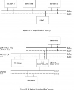
Multiple level or hierarchical bus topology ia an extension of the single level concept. If single level buses are interconnected in a certain manner data on one bus system will pass to another bus system. These buses differ from the multiple bus systems shown in figure I-3.1b, because they are not equal. Thus, one bus system is subservient to another bus system. This approach can be achieved using several different architectures as seen in figure I-3.2. Several systems today are using this approach to achieve functional partitioning (e.g., navigation to/from weapon delivery, avionics to/from stores management, etc.).
All 1553B data bus systems relate or communicate with each other via two control schemes; equivalent levels of control and hierarchical levels of control. The most common approach is equivalent levels of control. In this approach, coordination is required only when data is transferred. The autonomous operation and individual error handling and recovery schemes remain for each bus. Since this mechanization is the simplest and achieves the greatest separation between data buses, it is widely used.
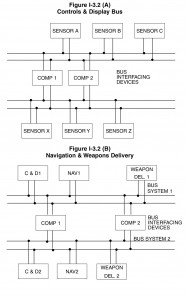
Hierarchical control schemes are viable and have been developed and analyzed in research applications, but until recently had few applications. With the development and application of MIL-STD-1760B (see paragraph 7.2) hierarchical control will be applied to control a weapons bus from avionic buses or store management system buses. The weapons bus may further control a 1553 protocol type bus within a store (missile or pod) to communicate directly with warheads, navigation, communication, or radar sensors. When these approaches are discussed in the literature, the bus level inequality ia usually expressed as local buses (subordinate – under submission of another bus) and global buses (superior – controller of local buses). Regardless of the control scheme selected, each of these methods fit into a single category; multiple levels or hierarchical.
3.2 Data Bus Control
3.2.1 Bus Control Mechanization
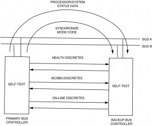
The second part of the bus topology description is the control philosophy. Two terms have been used in the literature to describe these control schemes; stationary master and non-stationary master. The stationary master approach to bus control occurs when a single bus controller manages the bus communication for all devices on the data bus. If this bus controller fails, depending on redundancy requirements, a backup bus controller can take over operation of the bus. This takeover procedure usually involves several actions involving the data bus, external wiring between the two controllers, and internal self test in both controllers (see figure I-3.3). The use of data bus messages to keep both controllers aware of the others status and health are usually required. Data bus synchronization using clocks or synchronize mode codes also provide the two controllers with usable switchover data. Internal self test software is responsible for identifying faults and removing the faulty unit from operation. Giving power control to the other processor (BC) with proper time delays also resolves conflicts in which should be in control upon initialization. Dedicated discretes with hardware watchdog timers provide yet another measure of switchover monitoring. All or most of these approaches are used today to achieve switchover. The development of a safe and secure method to switch to the backup bus controller is an essential part of any stationary master control philosophy. When this bus control approach is applied to a single level bus system topology, a single bus controller will be used with a backup bus controller, as necessary. However, in a multiple level topology, stationary master bus controllers are located on each data bus system with a backup controller for each bus as necessary.
An alternative to a stationary master bus control system is a non-stationary master bus control philosophy. In this scheme, multiple bus controllers can control the single data bus system. Therefore, even in a single level topology several bus controllers can exist. Obviously, to allow all of the controllers the capability to control a single system, a method of passing control from one controller to another is essential, because 1553B allows only one controller to be in control at a time. MIL-STD-1553B uses the dynamic bus control mode code to accomplish this task. As discussed in section 1.4.2, the MIL-STD-1553B protocol provides a method for issuing a bus controller offer, thus allowing a potential bus controller to accept or reject control via a bit in the returning status word. The key to non-stationary master operation is to establish the number of controllers required by the application and when to pass control. As in the stationary master system, once control is transferred the operation is identical.
Two methods have been used; time based (producing a system similar to TDMA) and round robin (producing a system with a preordered list of bus controller). More complex schemes have been discussed where dynamically the existing controller polls (using conventional messages) to establish a priority of control and then passes the control to the controller with the greatest need. However, most of these approaches are very complex and require extensive error monitoring to provide confidence that the system as a whole is operational (only a single controller is in operation—no more or no less).
The round robin control mechanization utilizes a fixed order of bus control. This is usually accomplished by assignment of incrementing or decrementing addresses to all potential controllers. Since a potential controller is a remote terminal, when it is not in the controller mode, it responds to its remote terminal address, when the dynamic bus control mode code offer is provided. In these types of designs, the potential bus controller must accept the offer to become the next bus controller. If the new controller has no messages to transmit, it offers control to the next potential controller. Failures of potential controllers are managed by the active controller in one of two ways; automatically going to the next potential controller (requires extra knowledge on how to accomplish this task) or by appealing to a backup controller whose job it is to resolve system problems and relate the results back to all controllers. This provides each controller with the knowledge needed to pass control. Obviously, there are always design trades between increasing intelligence in each potential controller or using a backup (single point failure) source to resolve the system configuration. This same problem also occurs at system startup. It is because of these complexities, that this type of system has had limited acceptance. However, with the growing use of multiple buses and the need to achieve data exchange between bus systems, this approach is being considered more and more often. Once again MIL-STD-1760B and other applications of multiple bus layers will yield a high degree of intelligence at the global bus level and thus a desire to maintain independence. All these affects will increase the interest of the system designer toward non-stationary master systems at global levels. This approach also has some unique system problems that must be resolved. Since each potential controller controls the bus each update period (maximum update rate of data transmitted in the system) and each controller has different message transmission requirements, bus usage times will differ. This difference will occur between controllers and between update for a single controller (see figure I-3.4). This shifting of transmission times makes synchronous updates difficult. Any system using this method to achieve integration must be analyzed to determine if it can accept these asynchronous data transfers without time tagging data or paying a heavy penalty in bus usage (efficiency).
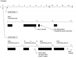
The time based mechanization allocates a fixed time for each potential controller to control the data bus. Once the maximum update is known then the period of time between updates can be allocated to individual controllers. The simplest approach is to divide the time equally. However, this may not have any bearing on the controller’s need to transmit data during the update period. This is where the system designer must trade controller complexity (different time bases for each potential controller) versus message update needs and message partitioning between controllers. This method allows the system to achieve synchronous operation at the cost of bus system efficiency if equal or fixed times are maintained. Bus efficiency is thus lowered by allocating fixed times to each potential controller. Obviously, during certain periods the controller will be in control and will have very few requirements (e.g., transmit or receive). Therefore, unused, unrecoverable bus time produces poor efficiency.
3.2.2 Error Management
Another aspect of data bus control mechanization is error management. Regardless of approach, an error management approach is required. Two types of failure condition exist; data bus system problems; and subsystem or sensor problems. The method used to identify, determine the cause, and achieve corrective actions are all part of the multiplex system control requirements.
The data bus system can provide a communication medium to support error analysis associated with failure of sensor(s). Since sensors are quite different, the only capability the data bus system has is to convey the results of sensor built-in-test results or identify a non-communicating sensor. However, the data bus system is totally responsible for managing its own errors, including message failures and core element failures (i.e., bus controller and standalone remote terminals).
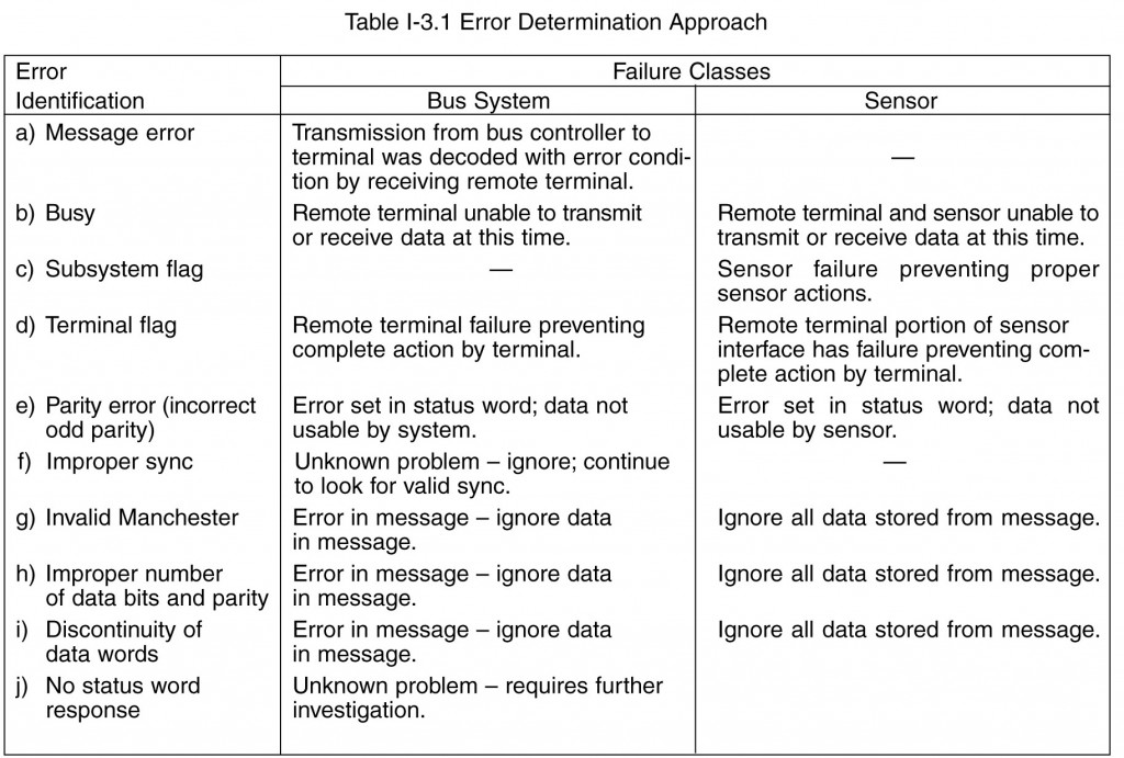
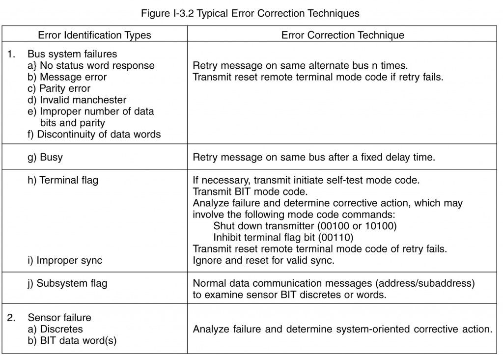
The 1553B standard requires correct word and message completion (1553B paragraph 4.4.1.2). These tests, plus system level checking, allow 1553 core element failure analysis. Some examples of test results and correction techniques are provided in tables I-3.1 and I-3.2. No requirement as to how error analysis is to occur is provided in the standard but the standard provides a mandatory set of tests for word and message validation (improper sync waveform, invalid Manchester data bits analysis, number of data bits per word, odd parity, measure of discontinuity between data words within messages, and no response by remote terminal to a message error) and an optional set of remote terminal status bits (service request, broadcast command receive, busy, subsystem flag, dynamic bus control acceptance, and terminal flag) to manage the data bus system. The action to be taken depends on the error identification and the error correction desired. All these decisions remain with the system designer. Error identification is the responsibility of all terminals connected to the data bus, while error determinations and correction are the responsibility of the bus controller based on the systems designer approach.
It is the systems designer’s responsibility to establish the systems response to each and every error identified by remote terminals or the bus controller. The error handling and recovery approach selected should be general in order to minimize hardware and software complexity. Usually the prime design issue facing the designer is: “How far should error analysis go before making a decision as to the corrective action required?” The ability to minimize analysis without discarding operational resources is the challenge. Therefore, the system designer should establish these approaches prior to hardware and software definition. Most current BC and RT components contain the necessary logic to detect bus errors and inform the subsystem or host processor of the error conditions. For remote terminals, this entails including discrete signals and/or interrupt request/status logic to inform the subsystem of invalid messages.
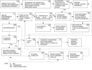
Bus controllers need to be able to autonomously detect if RT Status Word bit(s) are set as well as to detect no response and format errors from responding RTs. In addition, most current bus controllers, such as the ACE series, incorporate capability for performing automatic message retries. One method to convey these requirements to the hardware and software designer is the control procedure. Control procedures (see figure I-3.5) define the response to all normal and abnormal messages. In addition, control procedures establish how the system is to initialize, reconfigure, synchronize, shutdown, etc. To prepare this level of detail the system must establish the hardware and software partitioning and communicate the specific hardware design required to the hardware manufacturer and the software requirements to the software designer. This is usually accomplished with a detailed hardware specification and a software requirements document. The combination of control procedures and the actual hardware implementation yields sufficient data to develop software requirements. Then the software design accomplishes the system design approach.
The failure response to problems within the core elements of the data bus system include the data bus, the remote terminals, and the primary bus controller must be established prior to implementation. For the stationary master scheme, the failure of the bus controller causes a fail-safe transfer to the backup controller. This usually begins when the primary bus controller recognizes internal problems and ceases operation. The failure to notify the backup controller of operational capability on a regular basis and the lack of bus traffic alerts the backup controller to the fact that it should attempt to gain control.
In addition, hardwired discretes between the primary and backup controller can be used to indicate “who’s in control,” the terminal’s health status (a discrete which toggles each frame), and if the terminal is “on-line” (capable of 1553 communication). The first signal is used during system startup to prevent collisions by the two controllers. Later, if the signal is removed by the primary controller, the backup then assumes control. The health indicator is used to verify that the two controllers are executing their software correctly. The command that toggles this line is usually performed after completing a portion of the background built-in-test. Failure to toggle this signal indicates a software problem, and that control of the bus should be changed. The last signal (“on-line”) is again used during system initialization and later during monitoring by the backup controller if all communication on either bus ceases.
A positive method of access control is essential. Figure I-3.3 shows a simple method. See paragraph 3.2.1 for a complete discussion of bus switchover for a stationary master system. Obviously, it is much more complicated with the nonstationary master control schemes. The problem is who will transfer control to the next potential controller” when the controller presently in charge has failed. As discussed earlier a system monitor is usually required to resolve these and other abnormalities. The design of the monitor then becomes a trade between system autonomy and error analysis and correction.
The failure of a remote terminal is usually detected by bIts set in the status word or the lack of transmission from the terminal. The terminal flag bit provides an indicator of a problem, which can be investigated using the mode code transmit built-in-test word (BIT). There are no restrictions or definitions concerning the contents of the BIT word. However, the data should convey information, which allows the bus controller to take corrective action. If internal redundancy exists within the remote terminal, the ability to use the operational portion of the terminal must be conveyed to the bus controller. Otherwise, the system must reconfigure to replace the failed device if such a system reconfiguration is possible.
Since most remote terminals use 1553 chip sets, the designer of the chip set has already established the BIT word format. Some chips allow host (non-chip hardware) to download some health data, others do not. The hardware and system designer’s should establish what is acceptable for their particular system and select chips appropriately. The STIC and ACE component products include capability for formulating an internal BIT word. The internal BIT word, which is transmitted in response to a Transmit BIT word mode command, includes indications of transmitter timeout, internal loop test failure, DMA handshake failure, transmitter shutdown, terminal flag inhibited, bus channel for the last received message, and various message error conditions. The latter includes high and low word count, incorrect sync type, parity/Manchester error, various RT-to-RT transfer errors, and undefined Command Word error. The ACE also includes capability for the host processor to re-format the BIT word via software.
The other core element is the data bus system. A data bus system failure is usually recognized by the lack of communication with terminal(s). In dual or greater redundant data bus systems alternate data buses can be used to re-establish communication.
3.3 Functional Partitioning and Data Bus Element Redundancy
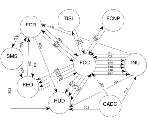
It is at this time that the functional partitioning philosophy must be established if multiple bus systems are to be used. If a single level system is selected, the following discussion concerning partitioning is obviously not relevant. For multiple bus topologies two philosophies are popular today; partitioning by function (control and display bus, navigation bus, weapon delivery bus) or partitioning by redundancy (separation of similar function—AHRS from INS ). These philosophies should not be mixed in a single design. It is the system designer’s choice based on the application since neither philosophy has proven to be better than the other. System partitioning by function seems to be more prevalent today, because of the engineering organizational structure, laboratories, and the need for parallel development. Also the system engineers can best be used if they provide the guidelines and general requirements rather than be responsible for a closely integrated system. This approach also allows loosely coupled subsystems. The functional partitioning approach allows direct messages between similar functions (RT to RT) and an easy transfer method to redundant elements, since they exist on the same bus system. However, since all the redundant elements are on one bus system, total bus system failure must be considered. In a dual redundant system this would require a dual failure, which is a remote possibility for mission oriented applications.
Using the redundancy philosophy, similar devices are separated from each other and placed on multiple bus systems. This provides greater autonomy and failure protection. It also creates more traffic between bus systems, if the redundant elements share data or check each other. This method then requires greater time for messages to pass from one bus system to the other and an efficient data passing mechanism is essential for multiple bus systems. Regardless of the method chosen, partitioning begins with functional interconnections leading to message definition. At this point, the selection of the bus controller scheme can be made. The type of control (stationary or non-stationary) and the level of redundancy of the data bus and the bus controller should be established. Generally, redundant bus controllers (active and backup) are used in stationary master systems. Most non-stationary master systems do not provide redundant controllers because of the extensive use of controllers already. In the event of loss of an important or critical function, the monitor bus controller in a non-stationary master system can assume a limited set of these functions providing a degree of redundancy. Data bus redundancy is usually dual. MIL-STD-1553B paragraph 4.6.3 states that if dual redundancy is used, the system must operate in an active/standby mode. However, the system is not restricted to dual redundancy and it can operate at any level of redundancy required to meet system requirements. If a dual redundant system is selected, the active/standby mode can be implemented in at least two ways; individual devices use either bus for communication (selection established by communication of the bus controller to the remote terminal) or block switch (all devices are communicated with over the same bus until a failure and then all are switched to the redundant bus). The most common approach is the first one, which allows the bus controller to communicate using either bus with any terminal. Since this method allows the greatest flexibility it is used almost exclusively. This approach does require the bus controller hardware and software to have the capability to distinguish, on a message basis, which bus it is to use.
The block switch mode is a slightly simpler bus controller mechanization, since it is not message or terminal selective, but system selective. However, this method limits flexibility and has not found wide usage.

Remote terminal redundancy is obviously equivalent to data bus system redundancy in the 1553 interface area. The design issue associated with the remote terminal is the extent of redundancy occurring in the circuitry approaching the subsystem side of the interface. Figure I-3.7 describes the functional elements within a remote terminal and shows three different design approaches to redundancy. In the first approach, the analog section is the only dual redundant section. This approach is NOT compatible with MIL-STD-1553B dual redundant systems, because the command word validation must be established for each bus to meet the requirements of the standard. This is accomplished in the second and third approach. The third approach uses completely independent interfaces to the subsystem, while the second approach duplicates only the minimum circuitry necessary to meet the standard. Another design is being used for remote terminals only, which includes two decoders and a single encoder. This method allows a terminal to receive on two buses while using only a single transmitter. This is an acceptable approach, but it has not received wide usage. This will change as more monolithic solutions evolve.
The advantages of the second approach are minimum hardware and good input/output flexibility, while the advantage of the third approach is isolation between channels. Most interfaces for both remote terminals and bus controllers are built using the second approach. This approach allows a bus controller to switch buses for retries without additional 1/0 support, a capability not available in the third approach. The third approach is used in systems requiring greater hardware isolation between the buses (i.e., flight controls). Care should be taken in using the third approach for active/standby system. The channelization could prevent proper operation of mode codes like transmit last command. If this mode code is received in an active/standby bus system, it must report the last command regardless of which bus it was received on (Single channel chipsets employed in a dual redundant design will not meet this requirement without the addition of external circuitry).
3.4 Data and Control Passing in Hierarchical Networks
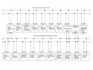
Notice from the figure that one bus network is controlled by the mission computer acting as the primary bus controller while the other mission computer acts as a remote terminal and the backup bus controller. For the other bus network, the roles of the two mission computers are reversed. Data collected in the navigation and weapons delivery system is made available to the control and display network via the remote terminal side of the mission computer. Therefore, the most general example of 1553 gates are single units acting as bus controllers on one network and remote terminals on the other network. However, two other approaches are possible: remote terminals on both networks and bus controllers on both networks. Figure I-3.9 shows each configuration. The least likely architecture is both remote terminals (configuration 11). This configuration will be discussed briefly because of its drawbacks. The remote terminals in this configuration receive data asynchronously on each bus network, thus requiring extensive data buffering or inter-bus network synchronization to prevent data contamination. This configuration requires data protection to prevent data reception on one bus network while at the same time the same data is being transmitted on the other bus network. There are hardware and software methods of dealing with this problem, but it requires extra effort to operate smoothly.
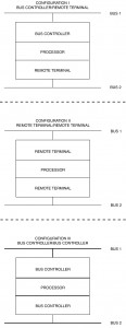
The architecture of configuration iii is most often seen in modern systems when a bus controller/processor controls multiple data bus networks in a synchronous fashion. Since control resides within a common computer, synchronization and data mapping control from one network to another is quite easy to accomplish. The most popular method is to operate all bus networks synchronously and globally map data in and out of large memory areas using message pointer tables (see paragraph 3.7.1 on subaddressing) that directs the data arriving from one bus network into a common area, which is accessible by the other network for transmission. This reduces or eliminates the internal data movement required to pass messages from one network to the other. In this configuration, navigation data can be passed to stores management networks without the computer moving the data internally. Another primary reason to synchronize the control of the two networks from a single unit is to reduce the data latency time between networks. Since control of both networks resides in one computer, the knowledge of when time critical data has arrived and is available for transmission to other users is always present.
The category I configuration is the most commonly used for a gate in today’s architectures because it supports a global network feeding the local networks or visa versa. Today’s hierarchical bus network structures are composed of two types of local networks: data source networks and data sink networks. This can best be explained by examining a few examples. If a navigation local bus existed in a hierarchical architecture, its primary function would be to provide source data to other networks. In other words, most of the data generated would have destinations outside the local network. Contrast this with a control and display network. Its function is to sink data from many other networks. Only man-machine control data is likely to be transmitted outside of this local network. As you can tell from the example, no network is completely unidirectional, but data bus traffic will predominate in one direction or the other. Local networks, like these, tend to be remote terminals on global buses in large architectural systems and bus controllers on their local networks.
As a rule of thumb, it is always better to be a bus controller if the unit is a source of data and a remote terminal if it is a sink of data. Obviously, the benefit of bus control is it allows the subsystems timing control thus providing source data freshness. The counter is also true, if the network is sink oriented, the role of a remote terminal is more than satisfactory. However, often these simple rules are not always practical in the architecture selected. Notice in the example of figure I-3.10. In this example, a mission computer is used to perform control of multiple global buses acting as a configuration III gate, while local buses (both sources and sinks) are configured as configuration 11 gates. Thus the design of a configuration 11 gate must be capable of data transfers in either direction. Generally, the data will have a definite direction, primarily in or out of the network, not both.
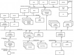
In the examples discussed so far, a large mission computer was used with its powerful, often processor based input/output section, to perform the functions of a configuration II or III gate. These units built by traditional airborne computer manufacturers often have very capable input/output circuits, which can perform either the role of bus controller or remote terminal. However, with the application of MIL-STD-1760B (see paragraph 7.2 for a discussion of the standard) in airborne 1553B networks, the need has developed for simple configuration II gates as shown in the weapons bus of figure I-3.10. The generic weapon interface unit is one of several units connected to the stores bus network as a remote terminal and to the weapons bus network as a bus controller. Many other simple hierarchical architectures may choose the same approach as opposed to complex mission computers. Therefore, a need has developed for a simple, almost hardware intensive, configuration II gate. The function of this device, (see figure I-3.9) is to receive and transmit 1553 data as a remote terminal on a higher level bus and transmit and receive 1553 data on a lower level bus as a bus controller. The features of this gate can vary from a unit as powerful as any gate built within a mission computer to a gate that can only carry out one message at a time from the higher level bus controller. With these extremes in mind and with the type of data flow that will be seen on the lower level bus (periodic or aperiodic), two basic design concepts have evolved in industry: transaction table controllers and peeling controllers. Each of these units will be described along with some of the reasons for determination of which is best for a given application.
The transaction table gate takes its name from the method it uses to perform the controller function. Transaction tables are lists of instructions, which are downloaded into the gate to direct the hardware to perform typical bus controller functions: transmit messages, receive messages, use mode code commands, skip messages (no-ops), jump from one list of messages to another, start, stop, use bus A or bus B, retry, interrupt on message transmission or reception, etc. All the features of a normal bus controller are built as instructions to the hardware. These called Channel Control Words (CCW) (see paragraph 5.1.1 for basic discussion on bus control and table I-5.1). Since each set of CCW’s describes a single message, multiple sets of CCW’s linked together form a minor cycle (see figure I-5.1). Since the flexibility exists to string messages together, periodic message strings can be built. Also error handling and recovery techniques are available using a fixed error handling message string. Generally, if a status word is not received or if received with errors, the limited computing capacity in this level of a gate requires error analysis and recovery to be accomplished in the higher level bus controller and passed back to the gate as a new set of CCW’s or a change of the existing CCW string (e.g., no-ops messages to a failed unit). The ability to dynamically download changes to the CCW or new CCW strings is also needed to support aperiodic and time critical messages through the gate to the subsystems at the lower level. Because of its construction of tables this type of gate performs very effectively when periodic traffic predominates the lower level bus network. To support time critical messages, they must be prepositioned or the bus controllers internal message position (instruction address pointer) must be available to the upper level bus controller in order to link in the time critical message. This is an overhead intensive function and should occur on as few occasions as possible. However, it is a very usable controller method and can be performed in a timely manner. All system timing should be met with this approach because it fundamentally is no slower, and often times faster, than the upper level bus controller, which initiated the traffic. Time critical messages, such as clock updates and weapons release, can also be performed using transaction table gates supported by a 1553 bus controller on the higher bus network. As can be seen with the use of transaction tables for multiple CCW downloads, aperiodic communications links, normal data traffic, and error recovery procedures considerable subaddress expansion will be required by the remote terminal (see paragraph 3.7.1.1 for a discussion on expanded subaddressing). Also the local bus performance and data exchange between networks will work smoother if the higher level and lower level buses are synchronized. Synchronization of the two buses is achievable using 1553B synchronize mode code with the data word command described in paragraph 3.6.
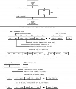
The second method used to meet the configuration II gate is known as peeling. The name is derived from the procedure used to generate instructions to the gate. Each message passed, from the bus controller on the higher level bus, to the gate contains up to two words at the start of the data message, which are peeled off the message (not part of the message data content) as instructions to be used by the gate in the processing of the message. Usually, the first word contains mode information (e.g., message type (BC-RT, RT-BC, usually not capable of an RT-RT transfer), bus to be used (A or B), retry options, etc.). The second word is the complete command word for the lower level bus. The remaining words of the message constitute the data words of the message (maximum of 30 data words). Note that MIL-STD-1760B (see paragraph 7.2) limits weapons bus messages to 30 words in order to support this gate technique. This approach works well for aperiodic and time critical messages because the message itself contains the data that is to be passed to the lower level bus. The peeling technique is much less effective when trying to get the lower bus to source (transmit) data to the higher bus levels. In order to get data from the lower level to the higher level network, a two word message is transmitted to the gate, which becomes the transmit command on the lower bus. At some later time, the higher level bus controller will transmit a new message to the remote terminal (gate) to collect this data. This two step process is somewhat difficult for aperiodic messages, but extremely time consuming for periodic traffic. Figure I-3.11 shows the protocol sequence required to support this technique.
3.5 Network Startup and Shutdown
- Initial communication with subsystems to determine their powered on state and health. Usually a unique subaddress, which provides subsystem health data, is chosen.
- Some subsystems require extensive initialization including program loads, system parameters, unique subsystem constants, time, etc. These messages are handled aperiodically with the subsystem prior to initiating periodic traffic.
- System synchronization (see paragraph 3.6 on synchronization of terminals).
Once a sufficient number of subsystems exist (have been initialized and are “on-line”) within the network to begin minimal operation, the bus controller can begin periodic message (minimal list) communications. After periodic communication begins on a network basis, all non-communicating terminals will be dealt with by error handling and recovery logic, which usually reports to application software that these subsystems are non-operational and presumed failed. Therefore, entering periodic processing too soon can cause false error reporting. If the bus controller later conducts a poll of all possible subsystems, late powered devices can be initialized and brought into the network, often upgrading the system to a more capable mode. Prior to periodic communication with these new devices, extensive aperiodic communication may be necessary. This could even be larger than at normal startup time, if the subsystem requires knowledge of the present state of the network.
Another important case, which needs to be considered, is the initial checking and monitoring between the primary and backup controllers. If one of the methods in which the backup controller determines it should takeover control of the bus is detection of bus dead time (a period of inactivity on either bus usually on the order of several minor frames), then the startup sequence has all the ingredients for a bus collision between the two controllers. To prevent this from occurring, one of two things must be done: a) always power up the primary controller first such that it will have completed its internal tests and will communicate on the bus first, or b) program a software time delay into the backup controller’s bus control program such that it will wait a “reasonable” amount of time after it completes its internal self test before attempting to take control of the bus.
Generally, error handling and recovery software deals with startup and shutdown in a different manner that normal operation, due to the apparent error conditions that exist because of asynchronous power control and subsystem warmup. If power control of the network is available within the processor acting as the bus controller, system startup can be a much more coordinated operation. The same is true for shutdown. If this is the case, usually the bus controller is the first system on-line and the last system off-line. This is often very important in military systems, which can contain classified data. Often the bus controller executive/application software is responsible for commanding classified data erasure in other subsystems and finally within itself prior to power removal. If the bus controller is not responsible for power control, the startup length will depend on how long it takes the system to reach a minimum capability.
3.6 System Synchronization and Protocol
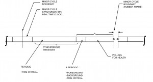
A given minor cycle can be described (see figure I-3.12) as the time the system requires to: a) synchronize appropriate remote terminals, b) transmit and receive all periodic communications scheduled for this time interval, c) transmit and receive any aperiodic requests generated by the bus controller or remote terminals (via the service request bit in the status word and the transmit vector word mode code), d) transmit or receive background messages (multiple messages exceeding 32 data words occurring over a period of time, i.e., mass transfers and bulk data such as data bases or program loads), which do not require completion this frame, and e) bus controller polling of subsystem status and health messages. Items d) and e) will occur only on a “time available basis.” Notice that the 1553 synchronize with data word mode code example provides a method of synchronizing remote terminals using minor cycle numbers. It also provides a method of updating an internal real-time clock with a resolution of 15 bits. Using the data bus to transfer system time can be done if exact time is not required. Resolutions under 100 microseconds are achievable if special hardware is provided in the terminal to store the arrival of the data word and read and save the internal reading of the terminal’s clock. With both the received clock word and the internal clock value upon reception, software can reset the clock by the off-set or ignore the difference due to the small error that exist. As can be seen in the example data word, (figure I-3.12) a method to achieve subaddress mapping commands is provided (see paragraph 3.7.1 for subaddress mapping discussion). By setting or resetting the time, update minor cycle, and update subaddress mapping bits, the data word can convey up to several encoded actions for a terminal with a single mode code transmission. An example of the events that would occur during a typical minor cycle using the features described above for the synchronize with data word mode code are as follows:
- Bus controller’s real-time internal clock interrupts its software indicating that it’s “time to start a new minor cycle”
- The bus controller software determines that all mandatory messages are completed from the previous minor cycle
- The bus controller transmits a synchronize with data word mode code to N terminals requiring real-time clock updates this frame (usually many frames can elapse between clock updates to a given terminal). This can be broadcast, thus updating all terminals using only a single mode code message.
- The bus controller transmits synchronize with data word mode code to all terminals (discrete or broadcast) requiring synchronization. The data word is encoded to indicate minor cycle update minor cycle number, subaddress mapping data, and the subaddress mapping number. Since the next traffic is periodic messages, the terminal can be designed to accept the same subaddress mapping number for a given minor frame (usually both encoded values are identical)
- The bus controller utilizes command words to perform all periodic communications required for this particular minor frame
- If time critical messages must be introduced during the periodic traffic, a synchronize with data word mode code MIGHT be used to a specific terminal to switch its subaddress mapping number to an aperiodic (interrupt upon message arrival) table. If this occurs, the terminal will need to be returned to its periodic subaddress mapping number with another synchronize with data word mode code. Notice that changes can be made with subaddress mapping numbers without affecting the minor cycle number.
- At the completion of periodic traffic, some terminals may be involved in aperiodic communications (foreground, background, time critical). This is accomplished by switching to the appropriate subaddress mapping table for each terminal. Each process may require use of the synchronize with data word mode code.
- The final activity in a given cycle may be to switch to a set of communications, which is really a background message list. This list contains a set of messages, which request and collect 1553 status and subsystem health and can be stopped when the time runs out for the minor cycle.
- Return to a) or dead bus time until a) occurs.
The BC architecture for the ACE series includes several capabilities to off-load the host processor for implementing minor and major frame times. These include the capability to program intermessage gap times on a message-by-message basis. The resolution for the intermessage gap time is 1µs, with a maximum value of 65ms. In addition the ACE supports major frame times by allowing a frame of up to 512 messages to be automatically repeated without host intervention. The major frame time for the ACE’s auto-frame repeat mode is programmable in 100µs increments, up to 6.55 seconds.
3.7 Data Control
3.7.1 Subaddress Selection/Operation and Data Storage
1553B remote terminal’s utilizes a 5 bit address (bit times 4-8) within the command word to identify data reception requests or data transmission requests. The bus controller also specifies which message set within the terminal is to communicate based on the 5 bit subaddress field (bit times 10-14). Two subaddress codes (00000 and 11111) are used to designate a mode code, therefore 30 subaddresses are available (30 transmit and 30 receive) for data use.
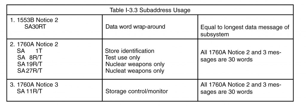
1553B does not assign any subaddresses. However, Notice 2 says “a data wrap-around receive and transmit subaddress of 30 (11110) is desired.” The maximum number of data words required to be received/transmitted is equal to the maximum word count the terminal is capable of for any subaddress. This additional requirement was added to provide the bus controller with a method of performing data pattern continuity (Manchester encoding/decoding) through a terminal’s front end (1553 hardware) and to the beginning of the subsystem interface (i.e., memory buffer). Also MIL-STD-1760B defines subaddresses (see paragraph 7.2 for a discussion of MIL-STD-1760B). System 2, the nuclear weapons specification, also specifies certain subaddresses for buses having nuclear weapons as remote terminals (see paragraph 7.3 for a discussion on System 2). Prior to release of these notices, the industry had consistently been using receive subaddress 30 as an interrupt and transmit subaddress 30 as a subsystem health message. Also industry has typically selected lower number subaddresses for data messages when only a few were required. Table I-3.3 shows the subaddresses identified in the standards and specifications from (7/87). As can be seen from this list, a growing number of selected subaddresses are being assigned, which may conflict with existing equipment. Also Notice 2 requires remote terminals implementing the broadcast option to be capable of distinguishing between broadcast and non-broadcast messages to the same subaddress.
The system designer has always been concerned about address and subaddress assignments. The proper use and selection of subaddressing can save considerable embedded protocol in data messages. Often mass transfers of data (greater than one 32 word message) occurs in 1553 systems. With proper use of subaddresses and memory mapping, multiple 32 word messages can be mapped into a contiguous memory area. This can be accomplished by assigning N (usually 16 or less) sequential subaddresses and then transmitting from or receiving these subaddresses and mapping to a contiguous block of memory. With the normal features of 1553B, an error can be detected and messages retired. Also this method does not require any particular order to the string of messages. In contrast, using an embedded protocol in 1553B data messages would require adherence to message order, sequence, and extensive error monitoring and correcting, which is not required with a set of sequential subaddresses. Another area where proper subaddress selection is necessary is for messages that require the terminal to interrupt and begin working on the data immediately upon arrival. These are usually aperiodic messages, which require immediate attention by the subsystem. To meet this demand, one or more subaddress may be dedicated to interrupt on reception or transmission.
A third category of messages are safety related. These might include flight safety or weapon safety (conventional or nuclear). In these cases, subaddresses are spaced digitally (i.e., maximum hamming distance) to prevent single or multiple subaddress bit encoding/decoding errors from causing the received data from arriving at an incorrect internal memory location or a transmitted message coming from an incorrect memory area. Each of these three categories of message along with the needs of complex subsystems has increased the pressure on finding sufficient subaddresses when only 30 transmit and 30 receive are available. Early in the 1553 development process this problem became apparent, when two computers communicating with each other via the 1553 data bus, exceeded 30 data messages. Therefore, the need for expanded subaddressing was realized. The basic idea has been used for many years. Previous designs have employed the first data word as a flag or control word to provide a new subaddress for the remaining data words. This obviously carries and overhead of word count reduction. However, in recent years a more generic usage of these techniques has developed, which allows application to any remote terminal needing more subaddresses. This method is discussed next.
3.7.1.1 Extended Subaddressing
The ability to request a remote terminal to remap its 30 subaddresses as a function of time, minor frame processing, or message type (periodic, aperiodic, background, time critical) has been accomplished by tying message mapping and synchronization together in the system. To synchronize a 1553B system two mode codes are available: synchronize with data word (mode code 17 – 10001) and synchronize without data word (mode code 1 – 00001). Synchronize with data word is used to allow the system designer to identify which minor cycle or frame the remote terminal is to enter. Most systems operate with less than 100 frames per major cycle (time required for all periodic traffic to be transmitted once).
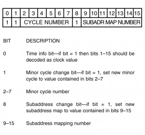
The data word in the synchronize with data word mode code allows the controller to switch subaddress mapping tables at anytime. The combining of synchronize and message mapping is shown in figure I-3.13, where the data word field is subdivided into a minor cycle number and an independent subaddress mapping field. This allows the mapping and minor cycle change to occur together or separately. If the subaddress field has one or more additional bits, the higher binary numbers (numbers greater that the number of minor cycles) can be used for aperiodic message mapping (foreground and time critical), background message mapping (multiple messages which do not complete within a minor frame), and large data transfer maps. Included in the large data transfer maps can even be program downloads.
3.7.2 Data Buffering and Validity
Message validity requirements within 1553B necessitate the buffering of the entire receive message until validity of the last data word can be determined. The matter is further complicated by the desire to ensure that transmitted data from a remote terminal is from the same sample set. Mechanizations which have been implemented to meet these needs include: first-in/first-out (FIFO) buffers contained within the Bus Interface Units (BIU) circuitry and standard memory devices, which employ a buffer switching scheme. The use of the first concept, a FIFO memory, is fairly straightforward. However, to ensure data continuity, a direct memory access (DMA) cycle long enough to read or write the total word count of the message is required. In today’s processor systems, this timing constraint poses no problems. For the reception of data, the 1553 protocol control logic must be capable of clearing the FIFO (resetting the pointers to the starting address) in the event of an invalid message condition.
The second scheme, which is more commonly employed, allows the BIU to DMA directly into a memory buffer, usually on a word by word basis. A minimum of two buffers is established for each receive and transmit subaddress, each buffer being 32 words long (see figure I-3.14). The starting location of the buffers, a tag word for each buffer (see paragraph 5.1.4), and a series of control flags is usually contained in the Buffer Descriptor Block (figure I-3.15). These flags specify which buffer is to be used by the BIU circuitry and which is used by the host processor. In its simplest case, when the flag is set to the receive state, the BIU writes its data into one buffer as each word is received, while the host processor reads data from another buffer. When a complete message has been received, validated, and the final word stored, the BIU circuitry toggles the flag so that the buffers are now swapped. Obviously, if an error occurred within the message, the BIU would not toggle the flag. For receive messages, the BIU controls the setting and changing of the buffer flag. For transmit messages, when the flag is set for transmit, the BIU reads from one buffer while the host updates the data in another buffer. When completed with its update, the host will toggle the flag. For transmit messages, the host updating the data controls, the setting and changing of the buffer flag.
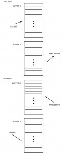
Now there are obvious conditions during which switching of the flag (and hence buffers) is not a good idea. For receive data, with the BIU in control this might occur after reception of a message, but NOT while the host is reading data from the opposite buffer, hence causing a mixture of old and new data. For transmit date, the host does not want to switch the buffers while the BIU is reading data from the other buffer. Therefore, some sort of handshaking between the host and the BIU is required.
However, before getting into the handshake protocol, there is a much more basic question regarding the transfer of data, which needs to be addressed. Does the terminal want to always receive the NEWEST DATA available (e.g., in the case of flight control parameters), OR is it more important to receive ALL DATA in sequence (e.g., the case of data base transfers or program loads)? In the case where newest data is required, the buffers are continuously swapped for each new message (assuming no errors). But in the case of wanting to receive all data, when both buffers are full (e.g., 2 messages received) AND the host has not read the contents of the first buffer, a problem exists because the next message would overwrite the first buffers contents, hence losing the data.
There are two simple solutions to the second case: first the use of more than two buffers; and second, the implementation of the busy bit in the status word. The first solution is simple, requiring only additional memory and the “housekeeping” logic to keep track of the sequence in which the buffers have been used (moving address pointers within a list). Some of the 1553 chip sets available support this approach. The second solution requires only additional logic within the BIU circuitry. The handshaking between the BIU, host, and busy bit is detailed as follows:

A BIU status flag is used to determine the status of the BIU with respect to the data buffer it is using. Similarly, a host status flag is used to determine the status of the host with respect to the data buffer it is using.
When newest data is desired, if the BIU and host status flags are cleared (inactive state), then the BlU/host is currently not using the buffer, while if these flags are set to the active state, the BlU/host is accessing the buffer. Note that these flags indicate the status regardless of whether the buffer is a transmit or receive data buffer.
Buffer swapping (the changing of the buffer flag) is performed as follows: Initially the BIU and host status flags are cleared (inactive state) and no valid data is contained in either buffer. For transmit messages, the host shall control the buffer swapping. To fill the current (selected) buffer, the host first sets its status flag to the active state, indicating its buffer is busy. When the host has completed updating the data, it changes its status back to the inactive state. When this occurs, the host looks at the BIU status flag and toggles the buffer flag if the BlU’s status flag indicates it is inactive (not using its buffer). If the BlU’s flag indicated it was accessing its buffer, then the host must wait until the BlU is finished prior to toggling the buffer flag. It is important to note here that Notice 2 requires that all data being transmitted on the bus must be valid. Therefore in the initialization process, the BIU must either be kept “off-line” until the host has updated one of its buffers and toggled the buffer flag, or the BIU must respond with the busy bit set in the status word until the host has updated one of the buffers.
For receive buffers, the BIU is in control of the buffer swapping. To fill the current buffer, the BIU first sets its status flag to the active state to indicate the buffer is busy (done at validation of the command word from the bus). When the BIU finishes writing data, it changes its status back to the inactive state. When this occurs, the BIU will look at the host status flag and toggle the buffer flag as soon as the host’s status indicates it is inactive. If an error occurred, the buffers are not swapped, and the erroneous data is overwritten by the next message to that subaddress.
When the collection of all data is desired, a BIU and host status bit cleared (set to inactive state) would indicate that the BlU/host has accessed and is finished with the buffer, while a status bit set to an active state would indicate that access to the buffer is currently in process or not yet started.
Swapping of the buffers and setting of the busy bit is performed as follows: For transmit data, the BIU and host status flags are initialized to indicate inactivity and activity respectively. This is done so that the BIU knows that there is erroneous data in its current transmit buffer. Here again, Notice 2 would require that the BIU respond with the busy bit set in the status word or be kept “off-line” until the host updates the first buffer. When the BIU or host is done accessing (updating) its buffer, it sets its status flag to the inactive state and checks the other flag. If the other flag is also inactive, then the data has not as yet been transferred out onto the bus by the BIU and the host must store the new data in the other buffer or somewhere else. For receive buffers, the BIU and host status flags are initialized to indicate activity and inactivity respectively. This is done so that the host knows there is erroneous data in its buffer. When a message comes in and the BIU has completed accessing its buffer, it shall set its status flag to indicate inactivity and checks the host’s status flag. If it is also inactive, the BIU shall toggle the buffer flags (swap data buffers) and set both the BIU and host status flags to the active state. BUT if the BlU’s status flag is inactive and the host’s status flag is active (both buffers full), and a new command is received over the bus, then the BIU shall respond with the busy bit set in the status word and not store the data. If an error is detected in a message, the buffers are not swapped and the BlU’s and host’s status flags are not changed.
Due to the diversity of terminal designs, and the levels and complexity of memory buffering techniques, the design and implementation of the BlU/DMA/host interfacing logic is left to the subsystem designer and is usually not considered as part of the BIU protocol logic.
3.7.3 Block Transfers
Block transfers, moving of large amounts of data via the 1553B data bus, are common with today’s data bus architectures. These transfers are used to exchange data bases between processor (e.g., primary and backup controllers), update navigational systems (e.g., GPS almanac data, digital map data bases, etc.), and perform operational program downloads.
One of the principal concerns in executing a block transfer is the handling of communications errors. This has to be accomplished such that there are not redundant or missed messages in memory. Auto retry capabilities are usually implemented in the execution of these transfers. Subsequently, when an auto retry occurs because of an invalid message, the designer must implement the control protocol such that the retired messages will not appear twice in memory with one being invalid and the other valid.
Various schemes have been employed to accomplish these bulk transfers. Commonly used methodologies are: time spaced messages to a single subaddress; multiple messages with subaddresses; and the use of expanded subaddresses (see paragraph 3.7.1). The designer must make trade-offs between the amount of memory available, levels of buffering desired or possible, and the amount of subaddressing available for use to insure that the bulk transfers succeed in moving the proper amounts of data, in the correct sequence, with no errors.
3.7.4 Data Protection
Additional protection of the data, other than the message and protocol checks contained with the 1553 standard, can be accomplished. Since data words on the bus are no different than the data contents of a 16 bit computer (with the exception of being transferred serially, and containing a sync and parity field), the traditional methods of computer data protection can be applied. These include checksums and cycle redundancy checks (CRC). Each have their advantages and have been successfully used in 1553 applications. The major disadvantage is that since their purpose is to protect data being “communicated,” they need to be included with the data (meaning the codes must be sent with each block of data versus a separate message). Therefore, the use of these codes reduces the amount of data which can be transferred in any given message.
During early applications of the standard, some terminals did not protect against the mixing of old and new data within a message. While checksums and CRC codes were capable of detecting this type of error, their overhead was considered too great to be used in all messages. Therefore an effective, low overhead solution was developed — the validity bit. A validity bit (single bit) was assigned to each data word. Implementations varied as to the inclusion of this bit into each word (often the MSB) or placing all bits in the last two words of the message. The placing of the bit within the word reduced bus loading and allowed a single word read by the applications software, but it reduced the resolution of the signal it was attempting to protect. When set, the bit indicated that the associated data was good. When multiple words were involved, the processor updating the data would set the bits to the same pattern (0 or 1), alternating patterns at each update. Hence it was possible to distinguish data not of the same sample set. Today, most terminal designs, by the method of double or multilevel buffering, assure all data transferred is of the same sample set.
For data that must have extended protection, multibit detection and correction, a hamming code protection scheme is recommended. Section 80 (formerly Chapter 11) of MIL-HDBK-1553 Multiplex Applications Handbook provides an error protection word based upon a BCH (31,16, 3) code, which will provide error correction up to 3 bits. The overhead is great. For each protected word, an additional word is required, but if this level of protection is required—use it.
3.8 Data Bus Loading Analysis
Analysis of bus loading is a relatively simple matter requiring only a hand-held calculator, some data about the system, and some basic system decisions concerning use of the standard. There have been several computer programs developed to calculate bus loading. These programs are generally used on very large and extensive systems with many messages. Bus loading programs are used more to manage the size of the message data base and its complexity than to calculate bus loading or build message sequencing. The basic data necessary for a simplified calculation of average bus loading is:
- Message/type
- Words/message
- Overhead associated with each message type
- Overhead associated with mode codes
- Intermessage gap
- Average response time
- Overhead associated with nonstationary master bus controller passing
The overhead constants to consider (in microseconds) are:
- Command word ……..20
- Status word …………..20
- Response time ……….2-10 (average 8)
- Intermessage gap ……2-100 (average 50)
- Mode codes
without data words …20 - Mode codes
with data words ……..40 - Data words ……………20
- Nonstationary master
bus controller passing ..(48 minimum)
- Bus controller to remote terminal and remote terminal to bus controller.
20N + 68 = Value for BC-RT - Remote terminal to remote terminal
20N + 116 = Value for RT-RT - Bus controller to remote terminals (broadcast)
20N + 40 = Value for BC-RT (broadcast) - Remote terminal to remote terminals (broadcast)
20N + 88 = Value for RT-RT (broadcast) - Mode code without data word
68 = Value for MAC without data word - Mode code with data word
88 = Value for MC with data word - Mode code without data word (broadcast)
40 = Value for MC without data word (broadcast) - Mode code with data word (broadcast)
60 = Value for MC with data word (broadcast)
Therefore, the average bus loading is the sum of the message type values divided by 1,000,000 (maximum no. of bits/see) times 100%. A system should not exceed 40% bus loading at initial design and 60% at fielding, in order to provide time for error recovery/automatic retry and to allow growth during the system’s life.
3.9 Interface Control Documents
Inasmuch as Section 80 has been successfully adapted by much of industry for standardization of message and data word formats, it has some shortcomings in identifying all the required data needed by the systems level designer. Some of this data is available at the initial design while other parts may not be available until verification or final buy-off tests of the terminal have been performed. The purpose of this section is solely to identify the types to terminal data which the systems level and bus control software engineers need.
- Condition which sets the optional status word bits (busy, service request, subsystem flag, terminal flag) and any required responses by the bus controller)
- Specific conditions for generation of mode codes and required responses to these
- Timing limits associated the mode codes (i.e., how long to reset or perform self test)
- Discretes to be monitored and a detailed operation of each (e.g.,’on-line’, BC/BBC, etc.)
- Modes of operation and specific procedures associated with each (e.g., built-in-test, initialization, normal operation, maintenance, priority operation, etc.)
- Specific power-up initialization sequence including required messages or programming (e.g., data loads, parameter initialization, operational controls, etc.)
- Maximum power-up time till ‘on-line’ including sequence (e.g., no response, followed by busy, followed by normal)
- Message timing constraints and interaction (if any) with the busy bit
- Self test procedures (internal, data wraparound, etc.)
- Data coherence and sample consistency procedures
- Service request procedures (command sequence or vector word definitions)
- Bus electrical characteristics (output voltage, impedance, etc.)
- Electrical interface requirements (connector type, pin assignments, voltages, currents, etc.)
- Programmable terminal parameters (terminal address, operational modes such as monitor or backup controller)
- Specific hardware self test procedures, BIT word definitions, maintenance code definitions
- Specific polling procedures for monitoring bus and terminal health
- All subaddress and mode code message and data word formats in accordance with Section 8-0 of MIL-HDBK-1553.
- First minor frame present and offset in each future periodic communications frame
- Unique shutdown requirements
- If message requires interrupt upon reception or transmission
- Unique or subsystem specific message strings (loading, mass transfer, sequence of messages, etc.)
- Mode switching constraints
- Validity bits (usage, rules for setting, interaction with data)
- Operational characteristics during “shutdown” transmitter mode code (i.e., is the terminal still capable of receiving and processing data from the bus)
