At the lowest level, the function of a bus controller is to cause data to be transmitted over the 1553 bus. For the purposes of this discussion, the collection of hardware and/or software that implements the transfer of information over the 1553 bus will be referred to as the Bus Interface Unit (BIU). The bus interface may be implemented via several devices or by one of the sophisticated 1553 control units currently available on the market. These devices automatically wait a specified time. (Per MIL-STD-1553B, this time is 14µs minimum. In current integrated bus controllers, there is usually a programmable response timeout to accommodate long buses; for example, the ACE terminals provide a choice between 18, 22, 50, and 130 µs for a response from a Remote Terminal. A dedicated processor or state machine may be utilized to off load the host CPU. In integrated terminals such as the ACE, the BC state machine is a built-in feature. This protocol state machine handles the tasks of message formatting, intermessage gap times, Status Word bit masking, error detection, retries, memory management, and interrupts. The host CPU has the responsibility of downloading 1553 messages to the BIU and transferring data between the BIU and other system elements.
As a result, today’s designers have a choice of two basic types of 1553 Bus Controller Units:
- Single Message Processors – This type of 1553 interface outputs individual messages without requiring overhead from the host CPU. The Bus Interface Unit determines the validity of the individual message and/or looks for anomalies in the status word. The host CPU is responsible for determining the next message to be transmitted, or the error recovery scheme to be implemented.
- Multiple Message Processors – This type of 1553 interface processes a series of messages over the 1553 bus without host CPU intervention. Each message is validated by the Bus Interface Unit. If no errors were detected, the Bus Interface Unit will automatically issue the next message in the frame. If an error condition is detected, the Bus Interface Unit may halt 1553 transmissions or may continue normal operation until the end of the frame. Alternatively, the BIU may perform automatic retries on failed messages. Various error handling techniques may be initiated by the hardware, or may be left to the subsystem to resolve.
5.1 Single Message BlU's
5.2 Multiple Message BlU's
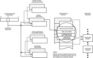
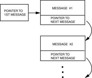
To accomplish this, the subsystem typically stores the 1553 messages in some portion of RAM that is also accessible to the BIU. The subsystem indicates which messages are to be transmitted by loading a stack with the addresses of the data blocks containing the messages, in the order in which they are to be transmitted. Alternately, the subsystem may chain the messages together, so that each message points to the next message to be transmitted. See Figures I-5.1 and I-5.3.
In either case, the subsystem must indicate how many messages are to be transmitted. This may be accomplished by loading a reserved word of the RAM with a message count, or by loading an “end of list marker” in the last message’s forward pointer.
Most current BC architectures allow programming of the intermessage gap times between individual messages. Some BCs, such as the ACE, include the added capabilities to start a BC frame from an external signal and/or automatically repeat a programmed frame of messages with a programmable frame (repetition) time.
5.3 Message Headers

In Multiple Message BlU’s, the format of this header information is specified by the vendor. In Single Message BlU’s, this header structure is defined by the user, and is implemented in software via the host processor.
The actual 1553 command words may be stored with the overhead information, or it may be stored with the data words associated with the message, depending on the architecture of the particular system. One or two words may be reserved for the command word(s) depending on the type of message (RT to RT for instance).
Most 1553 messages are time tagged. This value may be the actual contents of the system clock at the time the message transaction began or completed, or it may be an a system defined 16 bit number. In any event, it is linked to the particular message either by a pointer or by storing the actual Time Tag with the rest of the message’s overhead information.
5.4 Stacks vs. Linked Lists
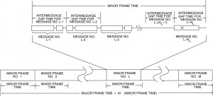
As shown in Figure I-5.1, the INTERMESSAGE GAP TIME word is stored in the third entry of the message block descriptor in the stack. In this way the CPU is able to schedule the time sequence of all messages to be processed. As illustrated in Figure I-5.2, this includes the structuring of minor frames. In a typical system, the minor frame time might assume a value like 5 ms. This supports synchronous message periodicities of 5 ms (up to 200 Hz); in this scenario, other message rates could be 10, 20, 40, 50, and 100 Hz. The use of a major frame parameter (Figure I-5.2[a]) allows the overall frame of messages to be automatically repeated by the bus controller without CPU intervention. For example, the ACE BC’s major frame time is programmable with 100 µs resolution, to a maximum value of 6.55 seconds.
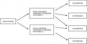
For instance (reference Figure I-5.5), assume that the frame consists of Messages 1, 2,1, 3, 1, 4,1, 4 and then the sequence repeats. The host can simply load the messages into the stack in that order, and issue a START command at the beginning of each major cycle. A disadvantage of a stack architecture is that it is not easy to insert messages into the middle of an existing stack. A typical application would be to insert an error recovery procedure into the message stream upon detection of a no response or other error condition. The host would have to physically change the value of the stack pointer to point to the new message stack. When the error recovery messages completed, the host would have to reinitialize the stack pointer to point to the next message in the original stack.
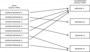
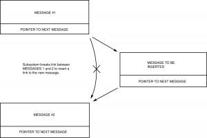
In a linked list architecture, each message points to the next message to be transmitted. This makes it very easy to insert messages into the middle of the message stream. The bus controller’s software simply replaces the forward pointer of the particular message with the address of the message to be inserted. The last message to be inserted would then simply point to the next message in the original list. See Figure I-5.6.
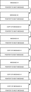
However, it is not as easy to implement the repetitive minor frames with a linked list architecture. For instance, let’s assume the that the frame consists of Messages 1, 2, 1, 3, 1, 4, 1, 4 and then the sequence repeats.
The host can set the forward pointer of message number 1 to point to message number 2. The problem arises with the forward pointer for message number 2. If it points back to message number 1, the host will have set up an infinite loop since message number 1 points back to message number 2. One solution is to make another copy of message number 1 and store it in a different portion of RAM. Message 2 can then point to this copy of message number 1. See Figure I-5.7. That copy would then point to message number 3. The problem arises again with the decision of what to do with the forward pointer for message number 3. Additional copies can, of course, be made. However, this architecture requires much more memory than does the stack approach, as well as requiring much more system overhead to maintain the individual messages.
A linked list approach is somewhat more complex to set up. The bus controller software must embed the addresses of the next message in the body of each individual message block. As these messages may be scattered throughout memory, the possibility for error is somewhat greater than it is in the case of a stack, where the host simply loads a fixed portion of RAM with the starting addresses of the individual messages. With a stack, it is also possible to see at a glance what messages will be transmitted, and in what order. A linked list typically requires a user to perform a memory dump of a much larger area of memory to trace the 1553 setup.
5.5 Status Word Analysis
If the service request bit is set, then the bus controller must either perform an interrogation to determine the specific service desired (transmit vector word mode code) and present the data to the main bus controller for a decision, or act upon the request based upon a table of actions known to the bus controller. See paragraph 3.6 for a detailed discussion of the protocol. The terminal flag and subsystem flag indicate faulty equipment. These problems are referred onto the main bus control program, unless an option exists to mask the problem (using an interrupt or to provide a branch to a set of instructions, which collects data or resolves the problem). It may also be a requirement to pass these two flags onto applications software such as a fault detection, maintenance, or caution/warning, or other general applications programs. In addition to these two flags, the terminal address might also be required so as to be able to identify the faulty terminal. Since the data was received with no errors (for the fact a status word was received), the applications software may use the subsystem flag as one of its validity checks in determining whether or not to use the data. For these reasons, some applications store the status word along with the data words in the memory buffer. In other applications, if the status word and/or tag words are stored, they should be separated from the data in order to allow contiguous data blocks of more than 32 words. The designer should analyze the systems requirements and determine the method of storage to meet his own requirements.
The remainder of the flags (dynamic bus control acceptance or broadcast command received) are normally passed to the main bus control software as a special condition, but the bus control software should be used in performing dynamic bus allocation as an operational function. The busy bit is normally handled the same as an error, since a retry could be quicker than the analysis to determine that the device was busy rather than an error had occurred. By the time the retry is initiated, the device should have removed the busy bit.
Current BC designs off-load the host processor by performing Status Word analysis. For example, the ACE BC can be programmed such that the individual Status Word bits for an RT response may be masked (“care” or “don’t care”) on a message basis. If a “Status Set” condition occurs (one or more unmasked bits are set), the BC can be programmed to retry the message and/or interrupt the host CPU.
5.6 Error Handling
The bus controller is responsible for the execution of the parameters indicated in the channel control words. Certain error handling activities are implicit for these parameters. The bus controller Is responsible for detecting that a message has not been completed; either by hardware indicating a bit error, word count error, Manchester waveform error, or lack o1 a status word. Then the bus controller will time out and request the status word (transmit status word mode code) or simply retry the message according to the rules given in the message header blocks. The most commonly used procedure is to retry once on opposite bus before trying next message in the list. Many variations are available once it has been determined that the message has failed to pass the retry procedure. These issues are discussed in Error Recovery (see paragraph 5.8.4).
5.7 Tag Words
In other applications, the terminal receiving the data will time stamp the data itself, usually using its systems clock as the tag. This tag word is then stored not in the data buffer with the data, but in an accessible location to the applications program, usually the Data Descriptor Block (see Figure I-3.14). If multiple buffering schemes are implemented (see paragraph 3.7.2), then a tag word for each buffer would be required. One other tag word approach is used, where the receiving remote terminal uses the minor cycle number, message validity indication, and an active buffer indication. These tag words are collected in a common buffer area for the applications software to examine when it begins processing of this minor frame data. In hierarchical architectures, where data must be passed between bus networks, data latencies can expect to be increased.
Terminals “tagging” the data, which are functioning as the gateway, present a problem. It may be necessary for this tag word to be appended to the data being passed through. In order to accomplish this, the tag word must now be stored with the data in the data buffer. By the terminal appending this tag word, the maximum word count of the original message is limited to 31 words.
The ACE BC provides a time tag word for every message processed. The 16-bit time value is stored at the beginning, and again at the end of every message processed. The resolution of the time tag is programmable from among 2, 4, 8, 16, 32, or 64 µs/LSB.
5.8 General Software Considerations
5.8.1 BIU Initialization
The BIU must be set up for communications and the flow of information controlled at a high level. The interface between the bus controller software and the BIU hardware/firmware is: (1) control words, which direct the BIU to perform certain functions during the normal course of message transmissions and reception. This type of information is conveyed in the message header blocks, and (2) an l/O interfaces, which provides the mechanism for the initialization to be performed.
The following types of data are typically communicated through this interface:
- Characterization Data
a) Whether the BIU is to act as a bus controller or remote terminal.
b) Terminal number (unique MIL-STD-1553 address). - Access Data
a) Pointer to the next message header block that should be accessed for normal operation.
b) Pointer to next message header block to be accessed for high priority message operation.
c) Pointer (base address register) to the list of pointers containing the message areas.
d) Pointer to the tag word area. - Operational Data
a) Start operation.
b) Perform self test.
c) Receive minor cycle number or the current time for tag word entry. If time tagging is used the BIU must maintain or read a clock to update the time.
d) Start high priority message.
e) Halt at completion of current message including retries or additional error management.
f) Halt immediately.
g) Resume operation from wherever the suspension occurred. - Status Data
a) Current message header block address that is being executed.
b) Self-test results.
c) Reason for interrupting.
d) Characterization data.
e) Access data.
f) Operational data.
As can be seen by the list, all of the functions that are necessary to get the BIU going, determine what the BIU is doing, and to redirect it are available. In some BlUs the only way to read status data is to wait until it is in a quiescent state after commanding it to halt its operations. Other BlUs allow the reading of data at any time. Clearly, for the operation of the bus, it is desirable to be able to (at least) determine the current and next message header block addresses, so that alterations in the chain can be made for asynchronous messages.
5.8.2 Controller Synchronization
Two or more processors (as well as the primary and back-up controller) may require knowledge as to what “address state” the others are in, as well as “what time it is.” In large systems more than 30 different input messages are required to be transmitted on the same bus to the same device. This condition leads either to the addition of more buses or a change of message subaddress meaning between each minor cycle (see paragraph 3.1.1 for protocol discussion). Synchronization is a method of signaling each processor that it is time to change the message memory map to the indicated minor cycle. Minor cycle synchronization also indicates that the previous set of transmissions have been completed. This signal allows tasks waiting for completion to begin processing on the data that arrived during the last minor cycle. This type of coordination can assure that the task will operate on data that is integral and not subject to change. Consequently, all synchronous tasks can wait for the start of the next minor cycle, unless a severe timing constraint exists that requires a task to process its data immediately upon arrival. In this case an interrupt must be set up to accomplish the scheduling of the affected task.
5.8.3 Scheduling Via Bus Event
A scheduler can potentially activate tasks based upon a number of events, which can occur over the bus such as minor cycle synchronization, arrival of a message, and completion of a message transmission. The most common occurring event is the minor cycle. All normal synchronous tasks can wait for this event, either In a wait queue or by having the cyclic tasks grouped together. Because this is so dominant, a special routine may speed the process. The remaining tasks will be waiting on event queues, one per event. The message arrival/transmission event can be signaled in some BlU’s by interrupting if a particular bit is set in the control word for transmission or reception on the bus controller, or as part of the message pointer in a remote terminal. The interrupt handler must determine the cause of the interrupt, then it will pass control to the bus controller to determine the reason for the interrupt. After this it will pass control to the event handler to set the event, which will schedule tasks that have been waiting for the event.
5.8.4 Message Error Handling and Recovery
The bus controller is responsible for the management of errors on the bus. If programmed, the BIU will perform retries according to the commands in the control word. If the retry procedures fail to achieve a valid transmission, then one of three courses are available; (1) the message header block may point to another set of message lists which will direct the BIU to perform further diagnostic tests, messages, or other recovery functions, (2) the message header block may point to a specific error recovery routine, which will be executed once the executive has determined the reason for the BIU error-interrupt, and (3) the executive can perform general error management by determining the type of error, type of message, source/destination, and by performing various types of diagnostic analyses according to time availability and need.
Many different error management schemes exist based upon the system requirements and individual designer’s choice. Three examples are given to show the variety, which can exist for error management routines:
- Some error handling mechanisms simply delete communication with that remote terminal until the conclusion of the major cycle, at which point a test message (e.g., transmit status word mode code) is sent to the RT to re-establish communications. The results of the test message weighted by some recovery algorithm (e.g., 5 correct responses in a row) will allow the readmission of communication with the RT.
- Ignore the failure and proceed. This moves error recovery from the channel controller to the applications software for determination that a problem exists, which requires additional action. The tag word is a valuable tool in this mode, since it provides a time stamp (in terms of either minor cycle number or BlU/processor clock time of arrival). The application software must determine when the non-arrival of data becomes important and must invoke higher level application software and bus control functions to acquire alternate sources of data if such exist. The problem encountered in ignoring faults in communication are twofold: a) data is not necessarily gathered relative to the device failures and b) multiple failures can cause excessive transmission delays, which can in turn cause minor cycle overruns. A variation on this is to perform error retries until a maximum number of retries have been used. At that point discontinue retries and finish the transmissions necessary for completion of the minor cycle.
- Respond immediately to the failure and initiate simple retry procedures based upon the channel control word parameters. The message header block may point to individual applications oriented executive software routines that involve specific error management routines embedded in the bus controller. These functions may be necessary to perform a self-test or to cause a message sequence to be retried from the beginning. This approach provides more flexibility in the management of errors than the first approach, since the first approach could be implemented in terms of the capabilities described in the second. The bus control interface must provide utility functions that could be Invoked by user-defined routines for specific message sequences. The more preprogrammed version of this type of error management the more a common recovery procedure is established for a specific class messages (there may be two or three general classes). These procedures can invoke self-test in other RTs, decide when a device is faulty and invoke reconfiguration functions. Generally, the quicker the problem can be Identified, the guilty established and recorded for later analysis (off-line) and the recovery performed, the simpler the system design will be. The availability of redundancy (similar or dissimilar) plays an important role in arriving at a quick solution. Remember, while the system is resolving the problem, it is not doing its primary job.
Current BCs, such as the ACE, provide capability for performing automatic retries. Having retries performed by the BC serves to off-load the operation of the host processor by eliminating the need for the CPU to react to “soft error” conditions. Retries are generally software programmable, usually on a message basis. Retries are attempted following no response and format error conditions. In addition, retries may be attempted if specific Status Word bits are set. For instance, a response by a MIL-STD-1553A RT with the Message Error bit set in the Status Word may result in a retry. Other programmable parameters relating to retries are the number of retries to be attempted (one, two, etc.), bus selection (same or alternate), and interrupts and other mechanisms for reporting the occurrence and result of retries to the host CPU.
5.9 Message Reception and Use
If a bus controller must also act as a remote terminal, the message reception mechanism must be different from a direct address scheme. The subaddress and pointer mechanism is the normal method for the reception and transmission of messages. In the most general case, each message pointer can also contain a descriptor as to the action, which should be taken when a particular message has either arrived or been transmitted.
An example of such a descriptor format is shown in Figure I-3.14. This method allows double buffering, which the remote terminal BIU must perform by exchanging the two pointer variables. Additional actions which may occur are setting an event flag or causing an interrupt on either the arrival or the departure of a message. These constructs allow two messages to come to the same subaddress without immediate software processing of the message. Such constructs also allow a “loose” coupling between the timing of the message arrival and the processing of the message. If only a single buffer were used the first message must either be processed or it would be written over with the arrival of the next message to the same subaddress. The interrupt, on the other hand, allows immediate attention upon arrival of a particular message (e.g., deliver the weapon).
In conjunction with the arrival of each message can be a tag word identifying some characteristics of the transmission. For example the validity of the message and time of arrived are two transmission parameters of use to applications software. The 1553B standard states that invalid messages are not to be used. In reality most designs require a message to be deposited word by word as they arrive. If a word in the middle of the transmission is in error, the remainder of the message may not be deposited. This situation would result in part of the new message and part of the old message being consolidated together. At best the data would be independent and not matter or at worst the data might be word-coupled (e.g., two words in a floating point number) and changing one part and not the other would completely change the meaning of each. A tag word allows the application software to determine validity and decide whether to use the old data, the new data, (valid to the point of error discovery) or neither in its computation. The tag word could also be the key into the error management/reconfiguration routines as discussed in paragraph 5.2.
Once the data has been received, the final step is to make the data available to the application software. In most 1553 systems, the data is available at all times to the applications software, and it is incumbent upon the applications to determine the validity of the data (e.g., was the subsystem flag bit set or is a validity bit associated with the data words) and which of multiple buffers to use. In these systems data integrity is achieved by waiting until all inputs are completed before commencing processing or by using buffers which have been filled and isolated by the 1553 BIU. If the system is very concerned about data integrity then completed buffers can be moved to the applications software for use. Then when complete they can be output from the applications software to the 1553 transmission buffers. However, the rather high penalty of copying each message discourages most users from applying this technique.